
Volvo
George Dill here in Temple, Texas, USA.
June 2010.
Eugene is in his second year of his new home in Austin, Texas.
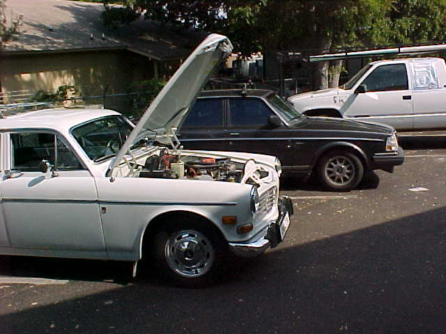
Here is an old pic at the old home...
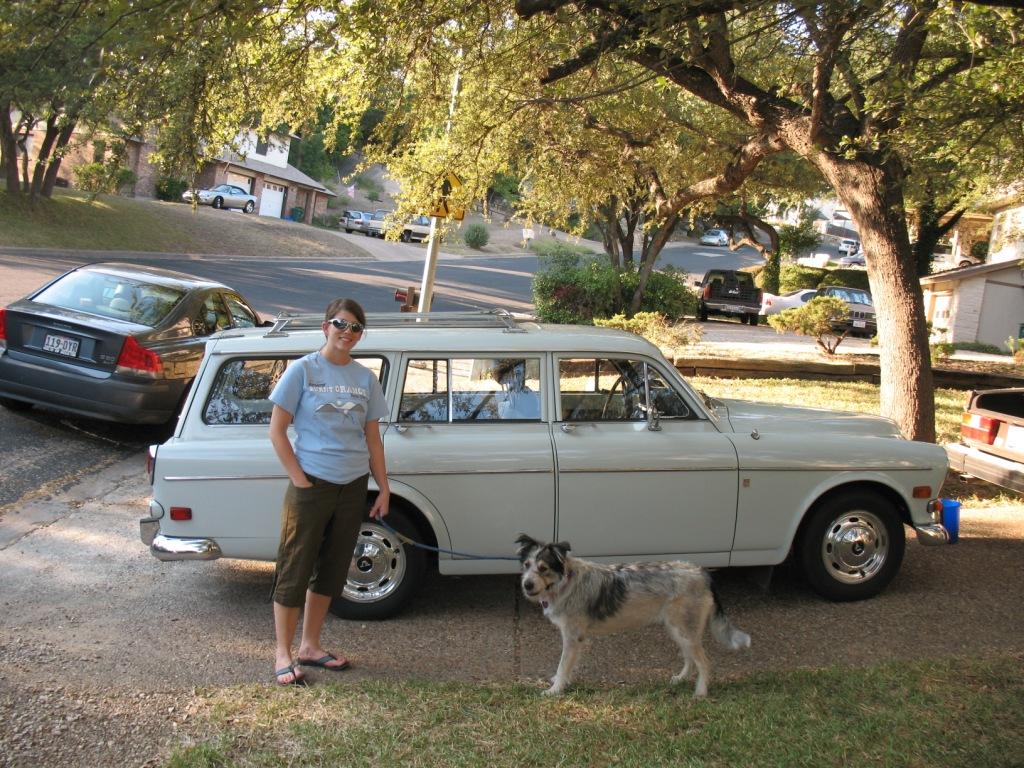
For that story click here.
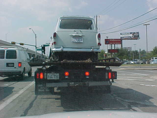
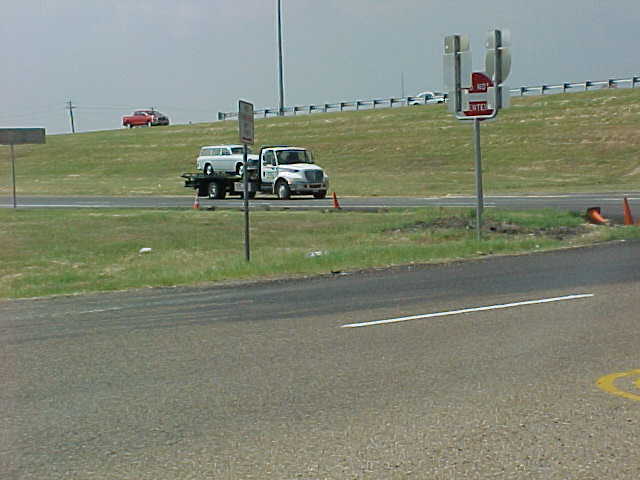
To view and steal pictures of this major transaction scroll to the bottom of the page you are on now.
Improvements to Eugene are on hold while Matt and Jen Harold plan a 2010 OSD trip to Sweden to see and drive their new XC70 all over Europe.
~~~~~~~~~~~~~~~~~~~~~~~~~~~~~~~~~~~~~~~~~~~~~~~~~
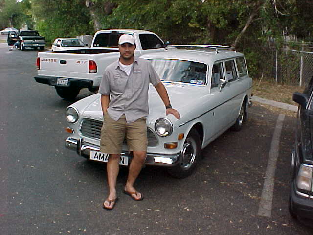
Matt and Jen Harold have owned this very nice all-original 1968 Volvo 122S Station Wagon (aka Eugene) for more than a year now and all is well.
For an informal history of this car since my ownership take another look here.
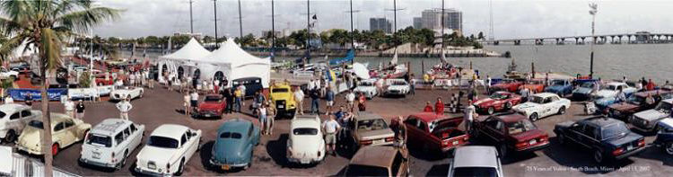
The panoramic picture above was taken in Miami Beach at the 75th Anniversary bash for Volvo cars in 2002. Here you can easily see Eugene's unique "off-white" color. Also note how few 122's are visible - one reason why Eugene won First Place Stock 122.
I will be adding to this page frequently and will put the new stuff at the "top" which may be confusing but will allow the reader to catch the latest without re-reading tons of warble.
On with the show!
~~~~~~~~~~~~~~~~~~~~~~~~~~~~~~~~~~~~~~~~~~
(NIB means new parts in boxes that come with the car.)
~~~~~~~~~~~~~~~~~~~~~~~~~~~~~~~~~~~~~~~~~
Posted on November 23, 2008.
Here we have SU air filters and Amazon Estate gas caps...
cap
~~~~~~~~~~~~~~~~~~~~~~~~~~~~~~~~~~~~~~~~~
Posted on October 12, 2008.
Here is an $$$ alternative to the XR700 electronic ignition...
...where you can also download the pdf install info.
And more on B18 engine here.
~~~~~~~~~~~~~~~~~~~~~~~~~~~~~~~~~~~~~~~~~~
Posted on October 11, 2008.
Just off the phone with Matt - carbs are leaking gas at idle. And from previous chat both front motor mounts are dust.
First the mounts - be sure to install a new trans mount with the new motor mounts.
The carbs are ready for a clean-up but it is best to have new gaskets on-hand first.
Here is a blow-up of the SU HS6 carb.
Note that this is a 2-bolt air filter version but will talk the same.
You can get another perspective on SU's here.
And visit here then scroll down for more.
Given that the motor has been shaking a lot during first-gear launch my guess is that crud at the bottom of the float bowls has come loose and stuck in the Grose Jet metering device.
Welcome back.
Now that you have seen and read everything SU let's clean 'em up good.
Be sure to have new float bowl gaskets (2), 3-hole air filter gaskets (2) and two new 3-hole air filters on-hand.
Remove the old air filters, short fuel line, and float bowl covers with screws, metal ID tab and floats attached. The floats are not interchangeable carb-to-carb. Don't even THINK about bending on the float mounting strip that touches the Grose Jet.
If either or both floats have gas inside toss and order new.
Wearing gloves and eye protection spray that horrible carb cleaner stuff into the carb throat by raising up on the piston with a stick or long screwdriver until the visible gunk has washed away. Don't tell Al Gore we did this.
Douche out the float bowls with clean paper towels then clean the gunk from the bottom as above.
Looking again at the blow-up pic above note that the float bowl clean-up may have pushed gunk down into the tube feeding the jet. What I do here is rig up an attachment to the wet-dry vac using the crack-sucker attachment and a short piece of rubber hose. Now you can suck out the bottom of the float bowl and hope all the crud comes out as any blockage here will cause the carbs to leak but you know that.
Be sure the Grose Jets and short fuel line are free of crud and that all old gasket material is gone from the float bowl lids.
Here you can decide to go even furthur into the clean-up and disassemble the carb completely.
I usually don't either.
Using new gaskets install the floats and lids and fuel line. Don't over-tighten the screws and always use a perfect-fit screwdriver. Bolt up the new air filters with new gaskets, check everything over, be sure the glass see-through inline fuel filter shows no visible crud inside, top-up the carb dampers with Mobil1 and crank 'er up.
You may need to use your hand on the carb linkage at first to rev up the engine (maybe even some choke) as the intake will be full of carb cleaner and gunk so watch the tail pipe junk getting on the garage floor.
If the carbs still leak call.
~~~~~~~~~~~~~~~~~~~~~~~~~~~~~~~~~~~~~~~~~~~~
Posted on October 7, 2008.
Body work and exterior re-paint.
During a recent email exchange with Matt I listed some areas that came to mind...
Driver's door has very tiny K-mart ding - a candidate for paintless dent repair but you will need to remove the inner door panel as when you replace the vent window seal.
Both vent window seals leak when hit with water jet.
Underside of front bumper has peeling plating, outside has scratches at both over-riders and LF mounting bolt has bogus threads.
Rear bumper has been pushed in very slightly at left side as has over-rider (two new rubber pads for over-riders NIB). Both reflectors need new rubber edging (NIB). Look for a tiny dent just above the left rear reflector (painted over).(NOTE: Right reflector repaired/repainted Mar '09 by Porsche/Audi body shop in Austin when damage to right side doors was repaired)
Rear hatch door glass appears to have been resealed by TXDOT flag person.
At least one body side strip is loose.
LR door window has frayed seal at rear edge.
All stainless steel trim has very sharp edges!
Inside surface of lower tailgate needs complete refinishing.ector (painted over).(NOTE: Lower tailgate repaired/repainted Mar '09 by Porsche/Audi body shop in Austin when damage to right side doors was repaired)
~~~~~~~~~~~~~~~~~~~~~~~~~~~~~~~~~~~~~~~~
Posted on October 6, 2008.
Alternator conversion to remedy existing generator problems (see amp light "on" below).
Here is an exact-fit alternator at a very good price, in stock and needing no mods to hook-up...
The picture for the above alternator shows a lower mounting housing that should mate up to the existing generator mount currently on the engine. This may require a single long bolt/washers/nut rather than the current two-bolt arrangement.
The ipd alternator conversion kit (NIB) is for '62-'66 122 only but may be modified to work with this or another alternator.
~~~~~~~~~~~~~~~~~~~~~~~~~~~~~~~~~~~~~~~~~
Posted on 5 October 2008.
Matt called enroute to Austin from Nacogdoches - amp light on. Gentle tap with magic screwdriver - all is well. Made it home ok.
~~~~~~~~~~~~~~~~~~~~~~~~~~~~~~~~~~~~~~~~~~~~
Posted on October 4, 2005.
Matt called yesterday during his lunch at work - he and Jen are heading for Nacogdoches in a '68 Volvo Amazon wagon - good luck!
~~~~~~~~~~~~~~~~~~~~~~~
Still 4 Oct.
XR700 electronic ignition - notes on installation.
(NOTE: XR700 and new Bosch Blue Coil were successfully installed on April 11, 2009. Matt mounted the XR700 control unit under the dash and routed the wires through existing firewall grommets. Also installed were new ignition wires, new distributor cap, and new plugs [NGK BP7HS]. The new distributor rotor had a thick wall and would not fit with the XR700 trigger in place. The old rotor was in good condition and re-used. Valves were adjusted and carbs were tuned but the engine ignition timimg was not changed.)
For a better take on the XR700 install click here.
Keep in mind that this blather is from a 66-year-old brain thinking back more than 30 years. Ignore me if the instructions say otherwise.
Matt - watch your email for a pdf install info from the Crane Cams (XR700) factory site.
Read the instructions about 4,000 times. Unpack all parts and set aside pieces that are not for this installation. Decide where to mount the control box for the XR700 noting the length of the wiring harness. If possible avoid drilling new holes in your beautiful Amazon but it's ok to "enlarge" existing holes.
This is also a good time to install the new coil and new spark plugs, check the engine ignition timing and adjust the valves - all very easy tasks. Consider doing some or all of these items AFTER the XR700 is fully operational and running in the car. IOW, don't start the XR700 install unless the car is running ok and don't make any other changes to the car during the XR700 installation. This helps when you need to figure out why the XR700 won't start the car.
Working from a cool engine disconnect the positive battery cable using the existing quick-connect lever.
Chock a back wheel front and rear leaving about 15" between chocks and tires.
NOTE: Fan blades are very SHARP!
Using a permanent thin-point marker label each plug wire and put this same number on the clean distributor cap at each wire.
Carefully remove each wire at the spark plug then remove the plugs noting condition and from which cylinder. See the Haynes manual on reading plug condition. The easy way to remove plug #1? Put the spark plug socket on by hand and turn it using a thin-faced spanner open-end wrench.
Remove the distributor cap (not the rotor) and center wire (at the coil). These are high-tech ignition wires and the push-in terminals are not a perfect fit for the existing aftermarket (ipd) distributor cap. The amount of wire exposed between the nipple and terminal is critical to insure a solid electrical connection. I highly recommend the purchase of a new Bosch distributor cap and Bosch rotor for this car.
Put the car in first gear and rock to-and-fro a bit noting the rotor's direction of travel when the car moves forward. (If you remembered the numbers on the distributor cap this will also tell you the firing order and distributor direction of rotation). Keep this up until the rotor points near the #1 cylinder position. Some distributors have a factory mark on the body at #1. You may need to re-position the wheel chocks.
Once you are close to #1 TDC put that thin stick (or a shortened WD40 straw) in the #1 plug hole and rock the car back-n-forth until the visible end of the stick is at its LOWEST position - #1 TDC.
Now look at the raised timing arrow on the timing gear cover that you cleaned when cleaning the timing marks on the crank pulley. You should see the arrow at or near the zero degree timing mark that you cleaned and highlighted along with the 20-before and 20-after marks. If the marks on the pulley are 180 out rotate the engine again and repeat the #1 to TDC routine.
Take the trans out of gear. Set the wheel chocks full against the tire.
It is best to not rotate the engine from #1 TDC during installation of the XR700 electronic ignition.
Note that tiny circlip on the mounting post for the points - remove this and save.
Dig through the NIB boxes for a large clear plastic bag with ignition wrenches.
Memorizing their positions, remove the rotor, condenser (capacitor and bracket), contact points and low-amp negative coil wire from the distributor. Use an exact-fit standard screwdriver on the screw holding the points to the distributor plate. Note how the components are isolated (insulated) from the distributor body at the hole for the threaded mounting shaft which retains the flat spring for the points. This shaft must not touch the distributor body when using the stock points/condenser set-up. This is also the hole through which the XR700 wires will pass. Save everything.
Noting its location and without losing any of those tiny screws, remove the distributor plate, clean/lube the advance spring/weights, lube the wick in the distributor shaft and oil the shaft at the twist knob. Replace the plate.
As noted elsewhere - the small plastic wheels (shutters) with the four slits in the XR700 kit are easy to break when being pushed down and/or pulled up from the distributor shaft. Use a socket to push down on the shutter.
Now comes the fun.
Ideally, the XR700 optical sensor that fits inside the distributor would install itself but nooo...
BEFORE installing the wheel determine the best position for the sensor (optical trigger) using the included brackets and screws. First, from inside the distributor, thread each wire on the sensor wiring harness individually through the hole in the distributor body. Minimize the amount of wiring harness inside the distributor as this allows more room for the sensor. Go ahead and test-install the sensor just to see how the brackets can be manipulated. Best fit is when the sensor is very close to the inside body of the distributor but not touching. Removing its mounting screw, lift the sensor from the distributor without changing the position of the mounting brackets on the sensor.
Now you will install the wheel (shutter #220) AND the sensor at the same time. As you press the wheel down on the distributor shaft introduce the opening in the sensor to the wheel so that both fall into position before the wheel's press-on detents grab the non-round part of the distributor shaft. Press the wheel down just enough to get the sensor's mounting screw started in the test position. If all looks OK press the wheel down a bit at a time while tightening the sensor mounting screw.
The final position will be that which allows the wheel to turn freely between the sensor's optical lens without touching the sensor yet fully attached to the distributor shaft. The wheel must fully block the light path between the sensors optical lens until a slit comes around allowing the lens to "see" each other which triggers the coil to fire.
Take a break.
If you plan to install the blue ipd coil (NIB) without using the diode kit now is the time to remove the stock coil from the firewall and cut it free of the hardened steel conduit and electrical wire (+ coil).
~~~~~~~~~~~~~~~~~~~~~~~~~~~~~~~~~~~~~~~~~
Posted on October 3, 2008.
While Matt is busy working on Eugene I must share with y'all that I purchased a 2009 Subaru Forester yesterday to replace my 1996 Volvo 965 wagon daily-driver (204,600+ miles) which went to the wife of a tech at Austin Subaru (former Volvo mechanic).
Looks like I'll need to start up a "URABUS" web site (what you see in your rear-view mirror when I am behind your car).
~~~~~~~~~~~~~~~~~~~~~~~~~~~~~~~~~~~~~~~~~~~~~~~~
Posted on September 29, 2008.
Visited ipd this mornin'...
*************
2008 VINTAGE CATALOG 7TH ED WILL SHIP
COIL BOSCH BLUE 68-81 ALL WILL SHIP
CRANE, XR-700 ELEC IGN 122S/1800E BACKORDERED
DIODE WIRE KIT 122/1800 PI088 FOR CRANE XR-700 WILL SHIP
INSTALLATION INSTRUCTIONS � XR-700 CRANE ELECTRONIC IGNITION WILL SHIP
ALTERNATOR BRACKET KIT B18-66 WILL SHIP
OXGARD ELECTRICAL CONTACT PASTE � OZ WILL SHIP
FILTER, AIR KIT ROUND (3-BOLT) SU FRONT AND REAR WILL SHIP
DASH PAD NEW OE 122 BACKORDERED
BP6HS NGK SPARKPLUG, B18/20/30 4EA WILL SHIP
NOTE: 122 OE DASH PAD AND CRANE XR-700 BACKORDERED � WILL SHIP ON ARRIVAL.
Ship to MATT HAROLD
C/O HAMMERHEAD BICYCLES
12307 ROXIE DR #102
AUSTIN TX 78729
Merry Christmas, Happy Birthday and Happy Wedding Anniversary!
I shop early!
Should some of these items not fit your plans for the car (new name?) just add them to the NIB and get rich on eBay later.
Along with the cracked dash I noticed that the air filters were funky which hurts drivability. These and the four new BP6HS spark plugs will help a lot. The existing points and condenser in the car are new. (NOTE: the NGK spark plug BP6HS will run ok in Eugene but the correct application is actually BP7HS with the proper heat range for city driving)
If you go with the new coil the ipd diode kit won't be needed as you can just cut into the shielded steel conduit under the dash between the existing coil and ignition switch.
This conduit houses the + wire for the new coil.
Notice on the existing coil you see just the center high-energy wire to the center of the distributor cap and the small signal (-) wire to the condenser post on the distributor.
The best way to access the shielded conduit is to remove the existing coil from the firewall. Be careful not to pull real hard as there is not much slack but enough to get a cordless open-end hacksaw on the conduit. Don't worry about damaging the + wire as you will be connecting a new wire to it for the + wire for the new coil.
Just a note about the Crane XR-700 electronic ignition - that little plastic wheel with the four slits will not tolerate strong pressure especially when being pushed down on the distributor shaft and when being pulled up for removal. Don't ask how I know...
More later.
************************
~~~~~~~~~~~~~~~~~~~~~~~~~~~~~~~~~~~~~~~~~~~~
Posted on September 28, 2008.
Just got an email from Matt with some updates/questions so let's take a look...
From Matt:
Hiccup 1: Starting from a stop. I'm not sure how much of this is me and how much is Eugene, but 75%of my starts from 0 involved so much rear end shake I was worried Eugene would be nothing but a pile of parts when I got done. Part of me thinks there is a disconnect between clutch and accelerator actuation. Whether that is to say I am not doing it right or the gas is not getting to the engine in a volume required or suggested by the accelerator pedal. Once Eugene is moving there are little if any problems with fuel delivery, shifts, or general performance (no noticeable vibration at speeds - suggesting I got the drive shaft balanced correctly).
From George: The carbs are too lean. When starting from overnight cool-off pull the choke out fully with no gas pedal. Once the engine catches use the choke and gas pedal to even out the engine at a good medium rpm. As the engine warms less choke will be needed. To drive away smoothly before the engine is fully warmed just pull out the choke about half or more as you press the gas pedal. This drops the jets and shoots a quick rich mixture to the intake manifold which will get the car moving forward without the jerking which is caused by the carbs being to lean.
Matt: Hiccup 2: Literally a hiccup. I was cruising along and I had what felt like a cylinder miss. IE I had a single momentary drop in go. Perhaps just kinks working out from time in storage.
George: Carbs are too lean. See fix below.
Matt: Hiccup 3: Brakes. I know you said the brakes are far less than what I am used to in a modern car. This was proven to me as I came to a light changing. I applied the brakes (not hard mind you) and the rear pass side locked up and left some rubber on the road and some smoke in the air. I pumped it a second or two and it unlocked and stopped as required. Probably just a gremlin relating to brake adjustment. Should work itself out.
George: See discussion(s) below on brakes. The brake shoes have over 20,000 miles of wear and are ready for renewal (NIB). Wheel lock-up will lessen as the existing brake shoes wear the rust off the hub braking surface. Give yourself extra distance to stop especially at higher speeds. You will find the other drivers filling in your gap but then you won't be going so fast. Brake problems will be non-existent when you get the new pads/shoes installed and adjusted. The wheel lock-up will go away but the braking performance will not be as your 240 as that system is far superior to Eugene's disk/drum setup.
Matt: After following the George Dill starting protocol I had the engine idling smoothly, though it sounded a little light. I had Eugene on a slanted driveway so I let gravity get us into the street. At this point things seemed alright, though the idle seemed less than stellar. I attempted to get Eugene going in a forward direction and it was nothing short of a battle. It almost seemed as though the throttle response was non-existent until the pedal nearly reached the floor. I could only get going in first and moving with a heavy foot on the gas and a very reluctant foot on the clutch. Once in gear and moving shifts were excellent, though as stated above the throttle was less than stellar.
George: Carbs are too lean. This is the time to pull out the choke just as you press the gas pedal (see above). Once the engine is fully warm you will need less choke to start from stop then eventually no choke will be needed to drive away smoothly.
Once cool weather stays around Eugene will accept a much richer setting on the carbs which will make drivability much better.
Meanwhile here is the fix: (car at home or bike shop and cool engine turned off)
Be absolutely certain that the choke handle is pushed fully in and that the choke is not acting on the carb linkage. Using that small jet adjusting wrench turn the jet adjusting nut FOUR FLATS richer on both carbs. This is much easier with the air filters off (don't lose the gaskets). Looking at the closest flat to you it will be turned toward the back of the car to rich the mixture. Replace the air filters and start the engine. As the engine warms through various temperature ranges the idle will change many times and you may need to use your hand on the linkage to prevent the engine from idling too low and dying. Using a standard blade screwdriver turn the idle speed adjusting screw clockwise to increase the idle on each carb. Start with 1/2 turn on each carb then move up 1/2 turn until the engine idle is very fast. Use your hand on the linkage to rev the engine a few times then let it settle back into idle. If the idle is way too fast back off the screws 1/2 turn at a time (both carbs) until the engine is at a high idle but not so high as to make the car difficult to drive. The reason for the high idle is to prevent what happened when we stalled on the busy Austin street and I had to lean out the carbs to get Eugene started.
Don't hesitate to make these carb changes as we can always return to a leaner setting but then this will mean using the choke again for smooth take off. A full tune-up (plugs, points, condenser, valve adjustment, carbs cleaned, etc.) will cure the drivability problems.
~~~~~~~~~~~~~~~~~~~~~~~~~~~~~~~~~~~~~~~~
A new era has begun!
Youth, vigor and attitude have taken control of the future of a human-made object brought to life by enthusiasm and optimism - yes!
Matt and Jen Harold will discover the wonderful world of positive people each time they stop for gas, relax at a 5-minute red light and park in the empty slots behind Threadgills - life is good!
Just yesterday Matt called to say the new u-joints are in as are the driveshaft bearing and bushing. ROLLING!
More later.
~~~~~~~~~~~~~~~~~~~~~~~~~~~~~~~~~~~~~~~~~~~~
~~~~~~~~~~~~~~~~~~~~~~~~~~~~~~~~~~~~~~~~~~
Posted on September 24, 2008.
Finally located Eugene's title and now I'm off to the tax office to get the forms required to sell a used car in Texas. The last Volvo I sold was the '67 144S back in 199? so I need a refresher on the current procedures. One such form is a certificate of sales tax which includes a dollar figure showing some percentage of the selling price. Since the selling price is $1,000 then the sales tax should be about $65(?). (NOTE: the State of Texas now has a sale price calculated for any and all used motor vehicles and the sales tax is calculated on this value if the sale price is lower).
~~~~~~~~~~~~~~~~~~~~~~~~~~~~~~~~~~~~~~~~~~
Posted on September 23, 2008.
Back from Lubbock - pics later elsewhere.
Just four days to get Eugene ready for the big change of ownership - gotta get busy!
Wait - too hot outside - time for a quick chat concerning Eugene and getting a smooth launch from stop.
Once the rear suspension bushings and u-joint work is done this will not be an issue but 'til then one needs an educated foot on both the clutch and gas pedals to get the car rolling forward smoothly without causing axle wind-up or "tramp" in the rear diff.
Just about the time you get good at this...
~~~~~~~~~~~~~~~~~~~~~~~~~~~~~~~~~~~~~~~~~~~
Posted September 18, 2008.
I will be in Lubbock, Texas, 19 through 22 September.
~~~~~~~~~~~~~~~~~~~~~~~~~~~~~~~~~~~~~~~~~
Posted on September 17, 2008.
AC upgrades.
Along with the possible conversion to R134a a consideration should be given to eliminating the huge and heavy York compressor (yes, NIB). Installing a current-version rotary compressor not only cuts weight a ton but lessens the pull on the engine per given BTU exchange. This along with the R134a fix and swapping the generator for a high-efficiency alternator with adjustable regulator would drop almost 100lbs from the front and add measurable hp to the engine under comparable full loads. All the brackets and hardware are available and not $$$. Here I would not be concerned about keeping the car "all-original" as these mods are easily reversed if desired.
NOTE! Eugene has Wagner self-adjusting rear wheel drum brakes!
NOT Girling as I have stated before.
Brake work.
Given that the brake fluid level in the master cylinder has not changed since I got the car we can be very certain that the dual-circuit brake system has no leaks.
The front brakes are easy to work on as this is the usual caliper/disk/pad arrangement. The only caution would be to avoid forcing the calipers open with a tool in an effort to install new pads. Instead open the bleed screw a bit (catch the old fluid) just enough to spread the calipers. This system is self-adjusting using the spring tension designed into the rubber caliper seals to maintain a constant pad/disk clearance. My direction is to install new disks (rotors) when needed rather than turn the old disks.
Rear brakes.
Take pictures of everything!
Operate the hand brake a few times then release all tension on the hand brake cables running to the back wheels.
Block the brake pedal to prevent downward movement.
Loosen the cap on the brake master cylinder and wrap with a large clean rag. If the reservoir is near full be careful how much you push on the rear brake shoes against the wheel cylinder pistons. Use the bleed screw as mentioned above.
Once you remove the tire and wheel (put a mark on the end of the lug closest to the valve core) take a pic of the hub showing the axle nut and cotter pin arrangement. Dumb? You'll see.
Using the homemade wrench provided back off the threaded brake shoe adjusting lug but do not remove (see pics of all this in the manual provided).
Remove the axle nut and washer. See that long slot in the tapered end of the axle? Therein resides a pin itself with a tapered surface on one end. You must return this pin to the exact position found. Take another pic.
Replace the axle nut wrong-side-in until flush with end of the axle. This is to protect the threads and end of the axle.
Using the hub puller provided remove the hub. What? It won't come off? One/both of two possibilities - brake shoes binding on the hub and/or hub bonded to the axle from years of contact.
Avoid the sledge hammer 'til later.
Being very certain that the hub puller is applying tension on the affected lugs and the center of the axle shaft an equal amount and in an equal direction go get the hammer.
With the puller cinched up tight smack the end of the puller screw once with a uniform blow. If desired place a best-fit deep-well socket over the end of the puller screw before smacking along with heavy-duty gloves and goggles on you.
You will know when the hub comes off as it will jump towards you with a loud pop.
Don't bother to make a second hit just loosen up the puller a bit and re-install with much tension on the puller screw as it acts on the end of the axle shaft.
Hammer, please.
Some folks get out the torch about now but I don't like the chance of cooking the rubber in the seals or overheating the grease in the bearings. If you get cast iron hot enough to expand that heat can travel to nearby parts quickly.
Still no luck?
George Dill, 254-541-2199 mobile anytime.
Now that the hub has released leave it in place until the puller has been removed.
Before carefully sliding the hub off look for that tapered pin residing in that slot in the axle. Camera please.
Once the hub is off (the pin should stay in the slot but may not be in its original location) take pictures of the brake components from various angles. These were installed (along with new brake shoes) by a master technician trained in Sweden by Volvo from 1962 off-n-on 'til 1978.
Compare the new brake shoes (NIB) with the old to be sure of fitment then note the position of each shoe (old and new) in relation to the brake material bonded on the shoe. You must be certain to install the new brake shoes in the same arrangement as the old as the system knows when the trailing shoe has been put on the front. You will too.
Is this fun or what?!
Remove everything, clean everything, check for leaks (brake fluid and/or axle grease) and notice that funny short rubber tube sticking out of the diff housing. This is the vent for the diff and must be kept clear of debris.
If the hubs are scored on the braking surface best bet is to get new hubs - yes, very $$$.
Install all the cleaned up parts along with the new brake shoes. Be sure the brake shoe threaded adjuster lug is in contact with the shoes via those two small riders that you reinstalled correctly. The hand brake cable assembly will be just as difficult to install as it was to get off. Looking at the picture you took, install the tapered pin, hub, washer and axle nut. Tighten the axle nut enough to get the hub/drum seated firmly then loosen the nut to the next opening to get the new cotter pin inserted and bent like in the picture you took.
Spin the hub to be sure nothing is binding.
Adjust the brake shoe lug inward (toward the wheel) until the hub is just barely binding on the brake shoes. Back of three "bumps". You will make the final adjustment once the car has been driven a few miles and the hand brake correctly adjusted.
Hook up and adjust the hand brake cables a bit loose, put on the wheels and tires (remember that mark on the lug closest to the valve core?) and go for a spin but not before you do the other wheel.
~~~~~~~~~~~~~~~~~~~~~~~~~~~~~~~~~~~~~~~~~
Posted on September 16, 2008.
Driveshaft repair. (NOTE: Matt has replaced all three u-joints, center support bearing and bushing as of Jan '09).
Note: Try to avoid making other changes anywhere on the car when working on the driveshaft. This will allow easier troubleshooting of post-repair vibrations if needed.
Sometimes called the "propeller" shaft (and the rear wheel axle the "half shaft") this component is easy to work on if you have a full-height lift in the garage otherwise be very careful when crawling under a raised car to do work.
Eugene has the odd "balance plate" on the front of the two-piece driveshaft which appears to be an effort to minimize vibrations. This arrangement would go away if/when an overdrive is installed.
This would be a good time to look at the new u-joints, center bearing, bushing and flange bolts/nuts to be sure they are the correct application. Yes, these parts are from ipd (ordered over the phone) and should be exact-fit but...
Since the driveshaft is balanced as a complete unit great care must be given to insure that the unit is re-assembled in exactly the same alignment as before driveshaft removal. This means that each part of the unit must be permanently marked before disassembly. This includes the mounting flanges at the transmission and rear diff. Some folks search for the old marks but I am paranoid so always make new ones.
One method is to use a cordless drill with a medium steel wheel and spin all the crud off the surface to be marked then dab a spot of white paint on the exact location. Some prefer to drift a punch mark into the steel but this can get confusing if others have punched previously.
What you will have is a series of white dots all in a line on every driveshaft component that can be taken apart. Notice that the front and rear shafts come together in a splined slip-fit arrangement. Be very sure of the alignment here as just one spline off will cause vibrations.
Now that the whole mess is on the bench be sure to avoid squeezing the shaft and yolks in a vise. The best place to get a grip is on the welds but even here don't over-tighten the vise.
I'll skip the details of u-joint removal but do note that the yolk on the ends of the driveshaft (that accepts the cross of the u-joint) has a yawl or cut-out on one face. This extra space is so you can get a grease gun on the zerk if the new u-joint is so fitted. If the grease fitting does not face the yawl you will need to use a needle on the end of the grease gun. Older Volvos had grease fitting on many components but now most replacement u-joints are greased for life which means you must install them carefully as this is what assures the proper grease seal.
You may wish to polish up any surface on the driveshaft that will be accepting a press-fit new component. This includes the yawls where the u-joint caps fit and the area at the center support bearing.
The pinion seal in the rear diff (NIB) is currently showing no seepage of any kind but now that the driveshaft is out...
I will skip the details of u-joint installation other than a note of caution - under each cap are many small needle bearing held in place by grease when the cap is removed. If for any reason you remove a cap (not needed for assembly) be very sure that none of the bearings are out of position when replacing the cap.
When re-installing the drive shaft use all new fasteners (bolts/nuts) at the flanges (NIB).
~~~~~~~~~~~~~~~~~~~~~~~~~~~~~~~~~~~~~~~~~
Posted on September 15, 2008.
Engine Specifications.
You can find all kinda numbers on the www but the absolute accurate figures are on these pdf's.
You will need to sign up on the UK Volvo Club site to get access but this is well worth the effort.
~~~~~~~~~~~~~~~~~~~~~~~~~~~~~~~~~~~~~~~~~
Posted on September 14, 2008.
Other "stuff" that I have done to Eugene...
The windshield wiper washer fluid jug is mounted on the fan blower box almost touching the top of the back of the valve cover. When the AC went in the instructions made no mention of where to relocate this item as its normal place was taken by AC components. The relocation works just fine and even makes the squirters (windshield washers) quicker and more powerful.
The AC control knobs under the dash have shiny little chrome inserts for "decoration" but these little circles have a habit of finding the floor so now live in the never-used ashtray.
Hinted at elsewhere - I have the driver's seat at the lowest of three positions available by adjusting a bolt/nut on each side and at the front of the seat.
I modified (rubber glue) the gear shift knob's internal threads in an effort to silence a rattle at certain rpms. No luck. What rattles is the loose connection between the knob and the pressed-in threaded metal insert that accepts the male threads on the end of the shift lever. This an easy fix but be nice to the knob as it is original Volvo and found only on the '68 USA 122.
The headlight foot dipper switch developed poor electrical connections (the headlights went out when dipping for high beam) so I took all apart and re-did the connections. If the NIB headlight relay is used to modify the dippers for operation by the turn signal switch (yes!) these connections in the foot dipper switch should be repaired again.
~~~~~~~~~~~~~~~~~~~~~~~~~~~~~~~~~~~~~~~~~
Posted on September 13, 2008.
Body - exterior.
Sharp eyes looking at the top pic of Eugene will note a small but visible gap between the top of the front bumper and the body. More than once I have loosened up the mounts and aligned everything perfectly only to see the gap reappear over time. Maybe some large, serrated washers in just the right place...
Here is a pic with the gap fixed. I was returning from the Texas Panhandle in August of 2005 after marrying up with the Dutch Volvo Club (Europe) at the Devil's Rope Museum in McClean, Texas (say "McClane").
Bilingual? To read all about the Dutch V44 Volvo Club's drive across the USA click here.

On that same front bumper the driver's side over-rider loosens up once a year. At least that's how often I put a wrench on it. Probably a new chrome-headed bolt/nut would fix this.
The back bumper over-riders are half-height with a rubber step pad on top for climbing up to reach the roof rack. The driver's side over-rider has been pushed up against the bumper (before me) and, once realigned, would look better with a new rubber step pad (NIB-2). The two rear reflectors could use new rubber edging (NIB).
The stainless steel trim on the car has very sharp edges where exposed on the ends especially at the rear of the rain gutter strip. When washing/waxing on the car keep an eye on the trim gap cover pieces as these tend to slide out of place.
All four mud flaps are new.
Air conditioner.
When my wife Trudi and I picked up the car in Houston (March 2001) we were welcomed by a very warm spring day in Texas. She headed back to Temple in her '93 Camry wagon (now gone) and I trundled along driving Eugene for the first time.
Out on the open road and cruisin' along at about 60mph I switched on the AC, felt and heard a "chirp" as the compressor kicked in then in seconds found myself fiddling with the thermo switch - this sucker gets COLD!
This is the original 1968 Volvo BRRRRRRRRRR AC system removed from the original crate new and installed in Eugene using the instructions in the crate.
In the summer of 2007 I noticed that the AC would cool down per norm then blow not-as-cold then return to very cold then...
My R12 AC buddy hooked up the gauges and found no pressure on the low side of the system. Just as he was about to remove the test hoses - sprong - the pressure jumped up to normal. He said the low side of the system has a "floater" that gets stuck for a while then frees itself to go look for another place to get stuck. Rather than waste R12 he said to bring in a new compressor and he would swap it out for $25 and the price of a full R12 charge.
Well, agooglin' I did go and found a brand new, exact-duplicate compressor in Arizona $235 plus shipping. In a week the box was on the front porch and in a few minutes in the garage. That's where it is today. (NOTE: now in MATT's garage).
Installing the new compressor entails recovery of the existing R12, vacuuming the system dry, RR the compressors, perform a leak test, vacuum the system dry again, recharge with R12 then make a final leak test.
This would be a good time to consider a conversion to R134a.
Before removing any AC parts in may be a good idea to take close-up pictures of the compressor setup to include the pulleys and drive belts. After much experimentation I finally got all three pulleys aligned and found a belt which best-fits each pulley groove. Looking at the idler pulley mount one sees a very large washer backed by a serrated washer. This arrangement must be returned exactly as now installed to prevent the drive belt from running crooked in the pulley grooves. Just how long did it take me to discover the cause of the fine black "powder" all over the engine compartment? Yes, the drive belt was grinding itself to oblivion on one edge of the compressor clutch pulley. The current setup has been flawless since late summer of 2001.
Interior.
You just gotta see it to believe it.
The lady that owned the car for more than 30 years in Eugene, Oregon, had no children and apparently had no passengers as only the driver's door had the marine shipping plastic removed. It appears that I was the first person to roll down the windows on the back doors.
The headliner looks like it was installed this morning but is indeed original.
The ash tray and cigar lighter have never seen a camel.
The dash, seats, door panels, cargo mat and side panels - all original and absolutely perfect.
The inside of the lower tailgate has a nickel-size paint touch-up spot that could use a talented hand with sandpaper, filler and final-finish paint. Good luck matching the color.(Repaired - see note above.).
The top of the back seat has an imperfection that is either an abrasion or fault in the material - patina!
The wall-to-wall rubber mat has deteriorated from the Texas summers and old age. The new mat is NIB that I got from a trusted source in Sweden in 2002. I have yet to open the box.
Installing the new mat will entail the removal of the front seats which would be the perfect time to renew the carpet underlayment and maybe even adding a coat of high-tech POR from ipd on the metal floors.
Installing the NIB vent window seals will then put the interior in the "needs nothing" mode. Be careful when removing the interior door panels and door handles as you are working with old brittle connectors and panels that have never been apart since day one.
While the driver's door panel is off borrow a Paintless Dent Repair spoon and rattle out that tiny K-Mart door ding. You'll find it.
~~~~~~~~~~~~~~~~~~~~~~~~~~~~~~~~~~~~~~~~~~~~
Posted on September 12, 2008.
Electrical - engine.
The ignition system is the Bosch 12 volt original using contact points and a "condenser" in/on the distributor and the original stock coil. This means that you cannot "hotwire" the car as the 12 volt power wire to the coil runs in a hardened steel conduit impervious to most hacksaws and torches. This solid steel conduit is attached to the "bottom" of the coil at the firewall mount and runs up to the ignition switch - all three components being a single unit - the coil, conduit and ignition switch. Most Volvos with this setup have been converted to an electronic system. It must be said that when all the original components are in good order the spark provided is more than adequate to power the engine under all conditions.
The battery is kept fully charged by the Bosch 12 volt generator under the control of the Bosch 12 volt generator regulator - yes, the original system. Given that the car has no requirement for extra electrical power (stereo, driving lights, etc.) this system is adequate under most conditions. On the way up the mountain to Cloudcroft, NM, I needed both AC and defrosters/heat and high beams to get through the ice fog and it was here where the amp light had its classic faint glow indicating full output by the generator and battery. Many owners have switched to an alternator with adjustable regulator - an easy and inexpensive conversion.
Electrical - Body.
You will search forever looking for a 122 owner who has never twisted off the ignition key while trying to start the car. Eugene does not have this problem as the raised shoulder on the ignition switch has not worn down and the tab on the ignition key that "grabs" the raised shoulder has not worn down. The spare ignition key is good also. Some folks install a starter button under the dash which eliminates the need to twist the ignition key to start the car.
The 12 volt battery in the car is in good shape as I keep a battery-tender hooked up. Another good habit is to keep the positive battery cable unhooked when not using the car. I have installed a quick-release connection for this and use this feature as an anti-theft effort when parking outside at motels, etc.
EVERYTHING electrical on the car works as intended. The fuses are sensitive to dampness so I keep them coated with a high-tech spray/foam from ipd. Being a 1968 model Eugene has hazard flashers, side-marker lights and a handbrake "ON" warning light (part of the low brake pressure warning system). The headlights operate without a relay but the high beams are very bright. The tail lights are new units from ipd and also shine brightly. I mention this because dim lights are a 122 characteristic not suitable for today's driving conditions.
~~~~~~~~~~~~~~~~~~~~~~~~~~~~~~~~~~~~~~~~~~
Posted on September 11, 2008.
Front suspension and steering.
The car has a manual worm & roller steering box and steering effort is considerable at stop and low speeds. For city stop-n-go driving I keep 40psi in the fronts and 36psi rears which makes for a smaller front tire contact patch and allows easy steering but makes handling and braking tricky in the wet. If the car were fitted with wider wheels/tires the steering effort would promote Popeye arms. Once the car is above 20mph the steering effort is minimal.
Front alignment.
When I picked up the car in Houston much work had been done on the front end including new ball joints and tie rod ends. The alignment was set to the "best handling" specs which puts the front tires at a slight disagreement with each other for toe-in, caster and camber but allows for sharper steering and lower steering effort. After nearly 15,000 miles the front tires began to show slight irregular wear patterns so I rotated them to the rear.
Steering wheel, steering column and steering box.
What appears to be very slight play in the steering wheel is actually an indication of my efforts to minimize wear in the steering box and my laziness in replacing the steering column bushings (2) which join the upper and lower portions of the collapsible steering column. These bushings cost about $5.00 each but the labor and time involved in the installation is huge. The existing bushings have many miles of life remaining. The steering box has a tension adjustment screw/nut which I prefer to keep just a little loose as over-tensioning promotes rapid wear of the steering box gears. Rather than 90wt lube I run warmed-up STP in the steering box.
4-speed manual transmission and clutch.
All here is in good order. The car has different diff gears than the sedan. 60mph in top gear is about 3,800rpm (no tach in car) so running along at 70mph+ is a bit noisy but very smooth as I crossed the Mohave (four times) at this speed with AC humping and getting about 22mpg. Many owners of 122 wagons have installed an overdrive or changed out the diff gears to lower engine rpms. In the olden days on my '66 work wagon I ran 16" Dodge truck wheels on the rear with very tall tires which added a few inches to the distance of one wheel revolution and made a big difference on the highway.
~~~~~~~~~~~~~~~~~~~~~~~~~~~~~~~~~~~~~~~~~~
Posted on September 10, 2008.
The exhaust system is not original but is holding up ok. A new stainless steel system is available but listed at $1,100 two years back. Stock systems are available from head pipe back but may have clearance problems to resolve if the ipd anti-sway bars are installed (NIB).
Brakes - The current pads, rotors and rear shoes have nearly 20,000 miles of problem-free use. New pads and rear shoes along with install kits are NIB and the car comes with the 5-lug hub puller to access the rear brake shoes. When the car has been idle for some time the iron hubs may oxidize on the brake shoe contact surfaces causing some rear wheel lock-up during panic braking. This will go away after a few stops. The car has first-year dual-circuit brakes with a vacuum booster and two inertia-controlled brake pressure valves intended to prevent rear wheel lock-up under heavy braking. The brake master cylinder plastic dual-bowl fluid reservoir has been at the same level during my ownership.
The car has all-new clutch master and slave cylinders including a new hose and return spring. The fluid level in this system is also showing complete stability. I did the work with parts from ipd.
Before the trip to Lake Tahoe (when was that?) I pulled the head and installed a new head gasket along with the usual stuff needing renewed for a valve job (new head bolts also). The head was worked over by a local old-world class machinist. Other than "spinning" the valves no machine work was needed as the head was true and the valve seats in good shape. The trip to/from Tahoe went smoothly although I had to install new generator brushes before heading back to Texas. It was up the steep grades on the mountain back roads that I first noticed the classic "tremble" in second gear indicating a weak u-joint and/or drive shaft support bearing.
Since I drove the car mainly on long trips I set up the carbs for highway driving (lean). The manual choke is set to act on the linkage instead of the jet. This allows me to set a high idle when stuck in traffic without holding my foot on the gas pedal. The extra engine speed helps the AC by pulling more air through the radiator when the car is not moving. I will set the carbs and choke to normal before the car goes to Austin.
Another indication of highway use (and my laziness?) may be seen under the hood where I have secured items for easy access. This includes a squeeze bottle of Mobil1 for the carb dash pots, a plastic container of Castrol GT DOT3 brake fluid for the brake and clutch cylinders, the classic carb wrench for turning the jet adjusting nut, a small screwdriver for setting carb idles, a bristle from a wire brush and a thin needle for clearing/adjusting the windshield washer nozzles, a small waterproof container with spare fuses, a hand cloth with single-use hand cleaner pads, a shake-to-light flashlight, spare valve adjustment threaded bolts, on and on...
Except for using the DOT3 to top off the old clutch master cylinder I have never had to use the other stuff during a long trip. Can you say "paranoid"?
~~~~~~~~~~~~~~~~~~~~~~~~~~~~~~~~~~~~~~~~~~~
Posted on September 9, 2008.
Here are areas needing attention to get Eugene fully roadworthy.
NIB = New parts are in the box.
Replace all suspension bushings (NIB).
Replace u-joints (3), drive shaft center support bearing and bushing using new fasteners (NIB).
Replace shock absorbers (NIB).
Install ipd anti-sway bars (NIB).
Install new AC compressor (NIB).
Install new webbing for both front seats (NIB).
Install new wall-to-wall rubber floor mat (NIB).
True-up (straighten) steel wheels (2), one on ground and one as spare. Check other three for straight spin. Note: Be careful about allowing young male Volvo enthusiasts to test drive the car in a small parking lot with tall curbs (Miami Beach - 2002).
Install five new tires or buy new wheels and tires.
Install new guard for handbrake release button (NIB).
Remove all stickers, decals, logos, etc. from previous owner's over-enthusiastic display efforts.
Install new halogen headlights (NIB).
Install headlight relay and wiring to allow high beam flash/dip using turn signal lever instead of foot switch (NIB).
Remove homemade cruise control (works just fine but very dangerous).
End/Begin.
~~~~~~~~~~~~~~~~~~~~~~~~~~~~~~~~~~~~~~~~~~~~~

~~~~~~~~~~~~~~~~~~~~~~~~~~~~~~~~~
End
Visit
